If this is your first visit, be sure to
check out the FAQ by clicking the
link above. You may have to register
before you can post: click the register link above to proceed. To start viewing messages,
select the forum that you want to visit from the selection below.
I have isolated the GND and VCC pins from the CH341A programmer (VCC is 3.3V) and instead I am using the VCC and GND ports from a Mixtile Garage Exynos 4412 board, which provides 1.8V.
This does not look like a good idea...
The other pins from the programmer will still be at 3.3v, which will fry the eeprom
At work I use a Dataman-40Pro, this model supports 1.8v eproms... but it's more expensive, obviously.
If you don't have another solution, I can maybe program it for you if you send me your eprom (or a blank one).
Do we know what model the chips is? Do we have a bios image or do we need to dump it from a working machine?
I didn't have time to open and hack my box yet...
At work I use a Dataman-40Pro, this model supports 1.8v eproms... but it's more expensive, obviously.
Way more expensive I may add
Do you think that a logic level converter, like this one would help?
If you don't have another solution, I can maybe program it for you if you send me your eprom (or a blank one).
Thank you very much for your offer, I will try some things first and contact you.
Do we know what model the chips is? Do we have a bios image or do we need to dump it from a working machine?
I didn't have time to open and hack my box yet...
I still do not understand how people managed to flash the Teclast X98 Air 3G (which is using a W25Q64FW chip still on 1.8V) with the CH341A programmer. Could it be they used some kind of logic level converter to lower signals from 3.3V to 1.8V (using a reference 1.8V from another source)?
I still do not understand how people managed to flash the Teclast X98 Air 3G (which is using a W25Q64FW chip still on 1.8V) with the CH341A programmer. Could it be they used some kind of logic level converter to lower signals from 3.3V to 1.8V (using a reference 1.8V from another source)?
Looking at the eprom datasheet, it clearly states that the voltage of any pin can't exceed VCC + 0.4V (so 2.2v). Maybe it supports 3.3v for a short time, but I definitely wouldn't risk it !
The SparkFun bi-directional logic level converter is a small device that safely steps down 5V signals to 3.3V AND steps up 3.3V to 5V at the same time.
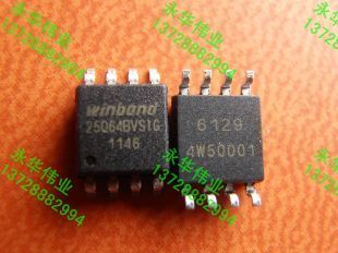
Can somebody provide the exact part number printed on top of the Winbond chip?
A close up picture of the Winbond chip, where the part number is readable would be nice.
I would like to experiment with BIOS modifications on some spare chips, to be on the safe side.
It would be nice to also report the corresponding PCB version, since there is a possibility that different chips are used in different PCB versions.
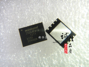
Mine is 25Q64DWIG, WSON package. It is a QFN SOIC 8 chip.
Chip ID: 25Q64DWIG 1151 6137 1570001.
It's the second package design shown on the reference paper posted earlier.
PCB v1.3, 20150109.
Last edited by Frontier; 02-28-2015, 18:43.
Reason: Picture
I am pretty sure that in the V1_2 board pictures that are attached to the 6th message of this thread, the Winbond chip has visible pins, thus it is a SOIC package type.
List of Devices supported by Elnec programmers. List of devices and manufacturers supported by Elnec device programmers. Device list, list of supported devices.
Anyway, looking at the official specifications, it seems that all packages of the same chip version have the same electrical characteristics, so they have to be electrically interchangeable.
The thing that concerns me is that 64D is the older version of 64F. If you look at the specifications, there are minor differences between 64D and 64F, so I do not know if they are electrically interchangeable.
Where did they find the older 64D version chips? Other devices, including Teclast X98, have the recent 64F variant.
Here is a pic of the chip we've been talking about. Mine is a v1.3 board. I wonder if it might be possible to modify a test clip to make contact with those pads on either side by pulling the pins out past the plastic slightly or cutting away some of the plastic or maybe even putting some little drops of solder on the ends of the pins.
I also found another chip on the back side of the board that seems to be an "ATML H430". I couldn't get a good pic of it due to lighting and the way the printing is. Do we know what that is?
Yes indeed, your chip seems to be the WSON variant, it has a rectangular shape, not square, and the pins seem to be flat, directly on the PCB.
On the other hand, by looking at the picture in the 6th post, the chip seems to be the SOIC variant, it has a square shape, and you can see the pins protruding.
This means that there are definitely minor PCB changes between the V1_2 board and the V1_3 board.
Last, but not least, your chip is the newer 64F variant, while Frontier reports that his chip is the 64D variant. This is weird, I will wait for a confirmation. If confirmed, then it means that the two chips are totally interchangeable.
I am going to buy some spare chips today, desolder and save the original chip untouched, and try BIOS modding on the spare ones.
I am still waiting for my device to arrive. Since I did not bother GeekBuying at all, it took them more than one month to ship my device.
Here is a pic of the chip we've been talking about. Mine is a v1.3 board. I wonder if it might be possible to modify a test clip to make contact with those pads on either side by pulling the pins out past the plastic slightly or cutting away some of the plastic or maybe even putting some little drops of solder on the ends of the pins.
If these chips can be programmed in place, you do not really need to desolder the chip, or even use an alligator clip.
It seems a standard package, so the chip contacts are approximately 1mm apart.
Since there are long enough visible contacts on the side of the chip, if you have a stable hand, you can set your soldering iron to a low temperature, strip a CAT5e cable, grab a long enough coloured tiny wire, put some solder on it, touch it on a chip contact, and heat it with your soldering iron until it sticks to the contact, which will probably take just about one second.
If you do not have a stable hand, or do not like soldering, just find a friend of yours who does.
In a couple of minutes, you will have all chip contacts cabled, without moving the chip from its place.
Manually connect the cables to your programmer according to their colours, program the chip, and then either cut the cables exactly over the contacts using a precise wire cutter, or better insulate the free ends and keep them in the case, for probable future use.
Here is a pic of the chip we've been talking about. Mine is a v1.3 board. I wonder if it might be possible to modify a test clip to make contact with those pads on either side by pulling the pins out past the plastic slightly or cutting away some of the plastic or maybe even putting some little drops of solder on the ends of the pins.
You have the 'FW' series chip, mine is 'DW' series.
I also found another chip on the back side of the board that seems to be an "ATML H430". I couldn't get a good pic of it due to lighting and the way the printing is. Do we know what that is?
Originally I thought that this is the EEPROM I need to reprogram for the BIOS (it needs a different programmer, so I've ordered one more for this one besides the CH341A). I have no idea about it's purpose but this one has SOIC pins and I will use my adapter together with the SP300U programmer to dump it's contents.
Yes indeed, your chip seems to be the WSON variant, it has a rectangular shape, not square, and the pins seem to be flat, directly on the PCB.
Mine is EXACTLY the same but it is the "DW" variant.
Searching for more information about the CH341A programmer, I came across a post on 4pda.ru regarding Teclast X98 Air where someone mentioned that the CH341A can program all Q64 variants using the W25Q64BV logic.
On the other hand, by looking at the picture in the 6th post, the chip seems to be the SOIC variant, it has a square shape, and you can see the pins protruding.
If you look carefully, you'll notice that PCB v1.2 has also an OTG socket installed - where v1.3 does not - and as I wrote earlier, you can use this OTG port together with Intel Manufacturing Tools to reflash the BIOS.
Very stupid move from PiPO to remove this socket as it would help a lot in the reflashing process.
There are also some RX/TX contacts on board, do not know their purpose either.
Last, but not least, your chip is the newer 64F variant, while Frontier reports that his chip is the 64D variant. This is weird, I will wait for a confirmation. If confirmed, then it means that the two chips are totally interchangeable.
I can confirm that mine is DW variant with the same package like dashellmutt PCB has.
Since there are long enough visible contacts on the side of the chip, if you have a stable hand, you can set your soldering iron to a low temperature, strip a CAT5e cable, grab a long enough coloured tiny wire, put some solder on it, touch it on a chip contact, and heat it with your soldering iron until it sticks to the contact, which will probably take just about one second.
This sounds like a good idea, I just have to find someone with a professional welding device because mine is not suitable (plus I am terrible at soldering).
You will definitely need a logic level converter because these chips operate at 1.8v, where most cheap programmers including the CH341A output 3.3V.
This sounds like a good idea, I just have to find someone with a professional welding device because mine is not suitable (plus I am terrible at soldering).
You do not need any professional welding device. Just a plain US $10 soldering iron is enough. You can even do it by yourself. You do not need excessive skills, just patience.
Strip a CAT5e cable and untwist it. Get a wire about 50cm long and strip the insulation about 5cm.
Use some appropriate surface to work. Cut a small piece of soldering wire with your hot soldering iron, keep it in touch with the tip of the soldering iron to form a large melted solder drop, and dip the end of the wire in the melted solder until it forms a relative small ball, slightly larger than the thickness of the cable. If the ball gets larger than expected, shake the wire to let it drop off. After a few trials, you will have a wire that has a tiny amount of solder on its tip. Put that wire over the centre of the chip pin, apply a small pressure, hold it with one hand steadily in place, and touch it with your soldering iron about 1cm or even more above of the chip pin. Do not apply any solder to the soldering iron and do not touch the chip pin. The heat will transfer to the end of the wire, melt the tiny amount of solder, and the wire will get soldered to the pin. This way, you cannot harm the chip pins.
After that, you have to insulate the stripped end of the wire. Strip the other end of the wire for about 5cm to 10cm, use a hair dryer to slightly warm the insulation across the wire, hold the free end with one hand and push the insulation to move across the wire until it reaches the other end.
Do that 8 times, and you are ready to go. It should not take you more than half an hour, and it just requires patience, not excessive skills.
People please! Desoldering chips and such??? I think we have lost sight of the OP.... The real issue is that we have a product that is obviously flawed in design since its end user can easily (and accidentally) render the unit worthless.... Safeguards should be in place to prevent this bullshit. If that's why the Beelink unit costs a bit more, then I'll pay a bit more...
PIPO: I better get my money back for this piece of junk.... Did you really think that the hacker community wasn't going to latch onto this product? The one community that would be most likely to encounter this situation??? Perhaps you should be spending more on R&D and QCA rather than trying to rush unfinished and incomplete product out the door....
People please! Desoldering chips and such??? I think we have lost sight of the OP.... The real issue is that we have a product that is obviously flawed in design since its end user can easily (and accidentally) render the unit worthless.... Safeguards should be in place to prevent this bullshit. If that's why the Beelink unit costs a bit more, then I'll pay a bit more...
I sincerely do not think that Beelink would be much better than the X7 in that matter.
It seems that all these OEM builders use the same common parts, including PCBs (alas with some minor customizations).
Better wait for someone to buy the Beelink first and report that it is different on that matter otherwise you risk being dissapointed.
PIPO: I better get my money back for this piece of junk.... Did you really think that the hacker community wasn't going to latch onto this product? The one community that would be most likely to encounter this situation??? Perhaps you should be spending more on R&D and QCA rather than trying to rush unfinished and incomplete product out the door....
I sincerely do not think that Beelink would be much better than the X7 in that matter.
It seems that all these OEM builders use the same common parts, including PCBs (alas with some minor customizations).
Better wait for someone to buy the Beelink first and report that it is different on that matter otherwise you risk being dissapointed.
I was just using the Beelink as a for instance... I'm going to sit back and watch this new genre of hardware mature a little bit I think.
We process personal data about users of our site, through the use of cookies and other technologies, to deliver our services, personalize advertising, and to analyze site activity. We may share certain information about our users with our advertising and analytics partners. For additional details, refer to our Privacy Policy.
By clicking "I AGREE" below, you agree to our Privacy Policy and our personal data processing and cookie practices as described therein. You also acknowledge that this forum may be hosted outside your country and you consent to the collection, storage, and processing of your data in the country where this forum is hosted.


Comment