Announcement

Collapse
No announcement yet.

Announcement

Collapse
No announcement yet.

H96 Pro+ housing upgrade (3D print)

Collapse
X
 
  • Filter
  • Time
  • Show
Clear All
new posts

    H96 Pro+ housing upgrade (3D print)

    Hi all,

    I was reading this site a lot before ordering my H96 Pro+ and I would like to and helped me a lot. So I want to share also updates for those who need it.

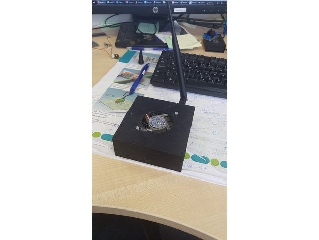
    I designed housing for 3D printing for H96 Pro+ which is little bit higher to insert cooling fan and additional wifi antenna, also hidden USB slots are now open.

    I would like to mention that this is first version with small failures where USB opening are not centered, so I needed to make some correction with Dremel.

    Now is OK but I will make V2 with proper holes and cover will be on top and not bottom for easier centering of PCB toward holes. Currently box is not surface finished, I recommend sanding and putty filler in can and then paint it.

    CPU temp is now avarage 40°C and WiFi signal is great.

    Files can be found here:
    Stock housing of H96 pro plus android TV BOX has bad cooling design and wifi antenna. So I made bigger box with fan and additional 2,4Ghz antenna. This is still in progress, needs to update holes a little bit. Current design is printed but a little bit modified with dremel."Distancniki.stl" are just legs which are glued sperately. Didn't want to have so much support for first layers so I made like this.


    Enjoy!
    You may only view thumbnails in this gallery. This gallery has 2 photos.

    #2
    Nice! I would like to see it after polish and spray with matte black.

    Comment


      #3

      What software are you using to model? I am interested in collaborating on your project if you want.
      ​​​​​

      Comment


        #4
        Hi, solidworks and Catia. Sure without problem, more ideas and versions is the best approach to design something better I will upload also step file so you can modify it.

        Comment


          #5
          Great! Unfortunately I don't use Solidworks, have you ever used Tinkercad? It is easy, free, in-browser and work well with stl, obj and svg files. Get the job done quickly.

          I have started making just a bottom case for use with original top part, I am trying my best to keep the low profile design of original box, but already convinced it needs some air flow.
          Found a cooler from old graphics card and am using a dc-dc step-up adjusted to output 9v ( min to run my 12v cooler). Also added some heatsinks with thermal pad (http://www.frozencpu.com/products/11...qXu5&mv_pc=149). Made the project public, all parts used to make this case are at the side:

          https://www.tinkercad.com/things/ibj...h96-pro-plus#/

          I like to slice my case designs in parts, based in printing time and electronics positions.
          This make better printed parts, less prone to wrapping, easier to reprint if something needs to be changed and also helps a lot when wiring electronics like 3d printer controllers.
          For a full box like your design I would slice in 3 parts, bottom (holding pcb), middle (with pcb ports alignment) and top (holding your cooler). Something like this case I made for CNC xPro board (see pic), but with your cooler inside the case and bolting from the bottom. When I don't have a 3d model of the pcb board or can't generate one, I take a frontal picture of the ports holes from original case or from the pcb ports view, import into a vector software to draw lines around all ports and save as svg. Import svg into Tinkercad and just resize to real size. Doing this my rate of getting alignment right first time increased, still sometimes I print a small flat plate just with ports holes to test alignment with pcb before full printing.

          You may only view thumbnails in this gallery. This gallery has 9 photos.
          Last edited by bernabap; 13 June 2018, 17:55.

          Comment


            #6
            Any v2 yet?

            Comment

            Working...
            X