Hi, need help with this board it´s a Mag 410 amlogic S905X red light on.
thanks
-
anything fw to getback from the hell. sir!Originally posted by Hotrod1 View PostLeave a comment:
-
Do you need the factory firmware or are you looking for a custom ROM?
Leave a comment:
-
how about firmware for this main boardOriginally posted by Abdalnablse10 View Post
i have board red plate v 1.2Leave a comment:
-
Been looking on here for a few days Trying to find the pins to short/jump on mxq pro 4k 5g rk 3128 wifi sv6158 with the chip samsung kmk7x000vm-b314


Leave a comment:
-
Hi all .
Please help me find pins for Beelink gt king Pro. I can't get in touch with the computer. Thanks a lot!
Unfortunately, I don't know how to upload photosLeave a comment:
-
Found the pins for the red pcb (clone) tx3 mini s905w 2gb 16gb (here is the url for the photo because I got blocked from uploading it here) the green line is where to short the pins. https://i.ibb.co/kxZ19sS/IMG-20200830-131514.jpgLeave a comment:
-
OMG IT WORKS THANK YOU SO MUCH!!! I'm in the brink of quitting, but your enthusiasm definetly helps me fix my board. Can't thank you enough.Originally posted by ath156 View Post
For those who's on the same boat with me here's what I did wrong and what works:
1. Flashing using USB C-A works, but you definetly need usb A to A (preferably short) that will power the board via USB itself
2. Short the pin 4 and 5, counting 1 from the arrow on the bottom right.
3. Don't worry about destroying your board, I've shorted so many pins that sometimes theres a spart from shorting them, all still well
Hope this help the next user with the same problem, and once again can't thank you enough ath156Last edited by wpra3; 03-06-2022, 12:45.Leave a comment:
-
1. Try adjacent pins in the area (1) (pins 4 to 8), as this is the most probable area. After that you can try also area (2) (28 to 32 pins). Also the 2 holes (area 3) are possible and in some other cases/boards they did the trick.Originally posted by phankhanh86 View Post
2. If you have 2 spare old/useless cables you can make a DIY new USB-A/USB-A cable and very short (less than 15cm long !!). Just keep their USB-A parts and connect the 4 wires inside color to color. If your USB-A/USB-C cable you have is very long, that may be the reason why you may need additional power !! If you make a new one very short you may also try other USB ports or other laptop/PC. Not every USB port of the laptop provides the same power.
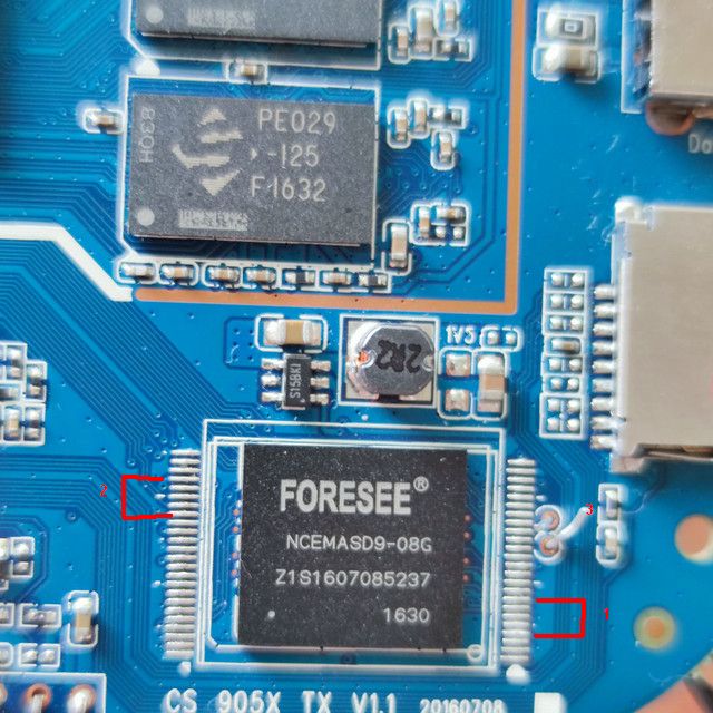 photo uploader for website
Leave a comment:
-
my process :Originally posted by wpra3 View Post
1. Start UBT
2.Shortpin
3 Plug power....
PC recognized
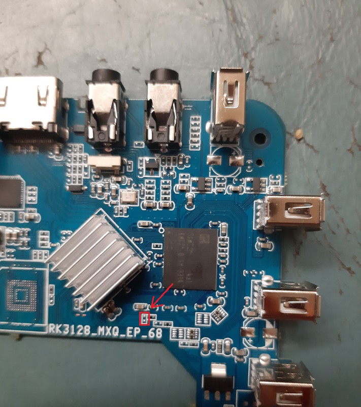
with plate mainboard have two hold near emmc....that shortpin
(my exper...)
sory my E not goodLeave a comment:
-
Originally posted by phankhanh86 View PostHi, really appreciate your help!Originally posted by ath156 View Post
Okay, for some reason my board is a bit weird.
It seems that most boards only need a usb connection for flashing, but mine is a bit more work.
I have to use the USB port that has "Download" written next to it, which is next to the sd card slot, hold the reset button, then plug the power.
If I did it correctly, I can see the device on AML burning tool.
As for the connection, I used USB A to USB C cable, and plug the USB C end to my laptop.
Please note that before bricking this device I tried to flash with atvxperience to this tv box.
As for shorting the pins, I've tried to short all the pins that are adjacent to each other. i.e. 1-2, 10-11, 11-12, etc
I have not tried to short pins that are far apart though, as it has a lot of combinations.
The procedure I used is also the same:
1. Plug USB download side
2. Hold screwdriver that shorts the pin
3. Plug in power
4. Wait a bit to see if it is recognized by the PC.
I also noticed that when I first try to short the pins, shorting some pin will cause a beeping/hissing sound (I do think its an inductor noise since the board itself doesn't have any speaker/buzzer). But now, the noise is gone.
Here's the closeup view of the FORESEE chip (Its NCEMASD9-08G)

Leave a comment:


There are currently 8867 users online. 4 members and 8863 guests.
Most users ever online was 16,134 at 08:28 on 08-11-2023.
Leave a comment: